Some Spider installations require an external antenna that can provide GPS and Iridium communication.
Spidertracks recommend AeroAntenna AT2775-110 and Sensor Systems S67-1575-109 antennas.
Both are low-profile, wide-band Iridium antennas providing coverage from 1565 MHz to 1626.5 MHz for excellent coverage of Iridium and GPS L1 frequency bands. Spherical-radius molded radome features enhanced protection against rain, ice and lightning strikes. The antenna is hermetically-sealed and DC-grounded.
Antenna Installation Information
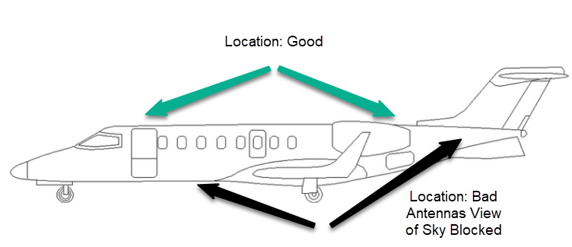
The Iridium antenna must be mounted on top of the aircraft for the greatest satellite visibility. For best performance, select a location with an unobstructed view of the sky, above the aircraft when in level flight and as close to the centerline of the aircraft as possible, and not to exceed an offset ± 5° max.
The antenna should be mounted in a location that would provide at least 8° horizontal view of the horizon and minimise blockage from the vertical stabiliser or other obstructions. Typically, antenna manufacturers recommend a minimum separation of 24" or greater from any other antenna regardless of system type.
The recommended spacing between the external antenna of the Spider and other antennas is a minimum separation of 24".

Using an External Antenna With Spider X Model
When connecting the external antenna to the Spider X, please make sure you are using correct antenna port for the antenna type.
1. External Cell Antenna
2. External Iridium Antenna
Also see this article on how to enable the external antennas for the Spider X.
Using an External Antenna With Spider 7 & 8 Models
The following diagram shows how to connect the Iridium antenna.
Other Antennas:
If you are not using either of the recommended antennas, other antennas need to meet the following specification requirements:
• Passive antenna able to receive L1 GPS signal on 1575.42 MHz
• Able to transmit L-band frequencies between 1616.0 - 1624.5 MHz
• Is ideally tuned as close to these frequencies as possible (bandwidth)
• VSWR is less than 2:1
• Has 50-ohm impedance
• A radiation pattern that is hemispherical (i.e. it points to the sky in all directions)
• Polarisation is right-hand for both Iridium and GPS.
Spider X Installation Only
The Spider X (firmware v6.7.1 and later) can collect and report summary diagnostics to assist with commissioning and troubleshooting.
Please Note: Minimum Requirements For Using Spidertracks Diagnostics:
Spider X firmware v6.7.1 and later is required for Diagnostics to work.
Spidetracks mobile application v5.7.0 or later is required to display these diagnostics.
More information on using the diagnostic tool can be found here: Spider X Diagnostics
FAQ
Q. I want to use a simple Coaxial Cable for the antenna, will this work?
A. There should be no more than 2dB of cable loss between the two components. Coaxial cable such as RG-178 can be used, however Spidertracks recommends aviation grade, low loss cable such as Times Microwave LMR-195-FR or similar for cables up to 4m.
In cases where more than 4m length is required, a lower loss alternative such as LMR-240 is recommended.
Spidertracks stocks cable kits with 4m LMR-195-FR, SMA and TNC connectors (to be fitted by installer). Contact sales RE PN "2000AKT100 - Antenna - Cable Kit - Spider X-7-8 ext".
Q. Does the antenna require an STC in order to be installed?
A. This depends on your Civil Aviation authorities. In the USA the installation can be done via a Technical Standard Order, using the FAA 337 form.
If you are having problems updating please contact support@spidertracks.com
Comments
0 comments
Please sign in to leave a comment.